Wednesday, May 8, 2013

Future Prospects

The are a few improvements which can be made in the project some of which are listed:

1. Use of sleep mechanism in the transmitter to improve the battery life and reduce power consumption.
2. Daisy chain the LED matrices to improve the display at each bus stop.
3. Make the android application more intuitive for the user.
4. Replace the laptop at the bus stop by a Ethernet shield on the arduino which can be used to send the data to the pseudo server.
5. Provide assistance to the operator as well by showing bus timings as a separate application.
6. Do traffic analysis to deploy more buses in case of heavy traffic.

Difficulties faced

We faced a few issues as we moved on in the project:

Problem:  The LED matrix and the MP3 shield would not work on the same hardware SPI even if we correctly altered the chip select pin.
Solution: We implemented software SPI for the LED matrix as we had a few extra pins on the arduino.

Problem: The Bus stop reading the serial port read trash values and incorrectly updated the database.
Solution: We adjusted the minimum number of bytes read to make sure that no trash value is read. Also we set conditions in the database to avoid incorrect updation.

Problem: Developing a server that could handle multiple requests from users
Solution: We spawned a new process each time a request is made to the server by a user. We kill it after it processes the request.

Problem: Android application would crash sometimes when sending and receiving data from the android server.
Solution: We created a new thread to handle the socket connections. Only after the thread finished did we move to the next screen to display the results. This significantly reduced the untimely crashes.

Problem: Network problems would not allow connection to a remote socket and crash the application.
Solution: Implement a catch mechanism in the JAVA code to go back to the previous screen in case of network problems.

Android Front End - Google Maps

Google maps was an integral and important part of the project. We used the maps feature for the following purposes:
Show user position
Show the closest bus stop
Plot bus routes
Show bus position
Navigate to a bus stop

We used the google maps API v2 for the project. It was more complex than the original API v1 but the maps were more interactive and feature rich as compared to the original version.
In this version, since maps are now encapsulated in the map fragment class ,we could show a map by itself on smaller screens such as mobile phones or tablets. 

Google provides many tutorials and API support online which makes implementing maps a smooth process. We did need to make a few modifications to suit our project and implement a few extra features but otherwise there is plenty of support available online.

Steps to get started (For a first time user):


  1. Download and configure the Google Play services SDK. The Google Maps Android API is distributed as part of this SDK.
  2. Obtain an API key. To do this, you will need to register a project in the Google APIs Console, and get a signing certificate for your app.
  3. Specify settings in the Application Manifest.
  4. Add a map to a new or existing Android project.
  5. Publish your application!
To get detailed information, go to:

Android Front End - Design

The android front end was the most important part of out project. It was extremely important for us to design a user friendly UI since without an intuitive front end, the work done in the backend would be of no use. We made sure that the user would have no difficulty in finding the bus timings he/she required by making the design as simple and descriptive as possible. We also made sure that the user would have no difficulty in understanding the navigation features of the application.

We were successful in hiding the details involved and made the user experience as simple as possible. Making different people try our application helped us understand and make changes depending on the feedback received.

We have a number of screens which show different information as requested by the user. Our application also has the Google map feature using which the user can find bus positions, the closest bus stop, the bus routes, and directions to the closest bus stop.


The application starts with a welcome screen that has a picture of a bus and the name of the
application. As soon as the application is started a picture is displayed on the screen and a thread is
created which sleeps for 4 seconds . At the end of 4 seconds, the ‘LOADING’ intent is started.


The intent MENUSCREEN has three radio buttons and a submit button that allows the user to
decide if he wants information according to the buses, according to the bus stops or if he wants to
get information using the maps. Based on the selection made by the user a new intent is started
(BUSSTOPINFO or BUSINFO or MAINACTIVITY).


If the user selects Bus Stop Information then the intent BUSSTOPINFO starts. This intent has two radio
buttons that allow the user to select the bus stop number for which they want to get information.


If the user selects Bus Information then the intent BUSINFO starts. This intent has two radio buttons that
allow the user to select the bus number for which they want to get information. On making a selection
and submitting it via the button ‘GO’ an intent ‘BUSDISPLAY’ starts. The screenshot is shown below.


Google Maps screenshots:
                                                              Displays the 3 bus stops


                                                            Displays the bus position


Display the Bus route


Provide navigation assistance


Embedded Front End Integration

The architecture of the entire integrated system can be viewed in the project architecture section of the blog.


The bus stop transmits a string of data continuously to the bus stop every second. The data structure used here is String. The string consists of two parts the first part denotes the bus number, and the next part of the string consists of the bus stop that it is heading to. For example the bus number 21 transmits “2133” before reaching the bus stop 33. The first part of the sting “21” is the bus number and the next part of the string “33” is the bus stop that it is heading to.

The code which is running at the bus stop continuously checks if it is receiving any data from the bus and when this happens, it parses this data to obtain the bus number and the bus stop and functions to display visual information on the LED Matrix and play audio information using the MP3 Shield are called.  It then re transmitted to the bus the bus number and the address of the next bus stop it has to go to.

We tested the system using 2 buses and 2 bus stops. The bus stops were around 200 meters apart. 
We had the pseudo server and the android server running at one bus stop to which the other bus stop communicated using TCP/IP.

Each bus stop looked like this:

The video for the actual demonstration was also recorded.


The Backend - Pseudo Server


The pseudo server is a remote server with which each bus stop communicates. This server is meant for data logging purposes based on the data received from each bus stop. Initially this server is also intended to create the database and appropriate tables in the database.
The data  received by the server from the bus stop is in the form (bus stop, bus no). Based on the data it received it updates the tables after time stamping the arrival of the information. This is done so that data retrieval at a later stage is accurate and the user gets to see the correct timing which is updated by once central server.


Database :

The server creates a SQLite3  database with a table for each bus and bus stop. Doing this the retrieval of data is much more simplified since memory is not really an issue for a central server.
The tables are updates using prepared statements in C.

For the purpose of simplicity, we have set the ETA for a bus on the bus stop as 1 hour from the current time and  the ETA for the next bus stop as 10 minutes from the current time.


The Backend - Android Server


This is a multi-process server whose primary purpose is to respond to queries sent by the user from an android application. It send the bus or the bus stop information to the user based on the request. It also sends data regarding the position of the bus .

This server has access to the database which is created and updates by the pseudo server. This server is ideally hosted on the same computer as the pseudo server. It spawns a new process to respond to the request from the user since multiple users might want to access the database at the same time. As soon as the request is processed, the process is killed.

The server is listening continuously on a port dedicated for this purpose.

The user application sends a code using the TCP/IP protocol because data loss cannot be tolerated. Each request is sent as a code which are shown below:

Code Purpose
21 Get bus 21 information
22 Get bus 22 information
33 Get bus stop 33 information
34 Get bus stop 34 information
100 Get bus 21 current position
101 Get bus 22 current position

The server sends a response by collecting data from the appropriate table and appending the strings to form 1 38 byte string with a ' $ 'as a last character to indicate end of string to the receiving android application.

Advantage of having 2 servers:

The data logging part is separated from the data retrieval part and hence the backend is more modular and reliable. One central server can be complex to manage as it might be difficult to handle data sent bus stops and user applications all on one port.


Bus Stop Design

Each bus stop has an arduino with a XBee shield which reads the data transmitted by the arduino+Xbee on the bus. The arduino on the bus stop is connected to a computer for this prototype design. The computer continously reads the port and send the data received to a central server using TCP/IP communication. 

It is very important to make sure that wrong and trash values are not transmitted to the pseudo server as it may lead to improper logging on the database. We have taken precautions on the server side as well to reject wrong data but its also important to do so at the bus stop side.


The code snippet for port reading is attached below:

int open_port(void)
{
     // file description for the serial port

        fd = open("/dev/ttyUSB10", O_RDWR | O_NOCTTY | O_NDELAY);

    if(fd == -1) // if open is unsucessful
    {
        //perror("open_port: Unable to open /dev/ttyS0 - ");
        printf("open_port: Unable to open /dev/ttyUSB11. \n");
    }
    else

    {
        fcntl(fd, F_SETFL, 0);
        printf("port is open.\n");
    }

    return(fd);
} //open_port

int configure_port(int fd)      // configure the port
{
    struct termios port_settings;      // structure to store the port settings in              

    cfsetispeed(&port_settings, B9600);    // set baud rates
    cfsetospeed(&port_settings, B9600);
    port_settings.c_cflag &= ~PARENB;    // set no parity, stop bits, data bits
    port_settings.c_cflag &= ~CSTOPB;
    port_settings.c_cflag &= ~CSIZE;
    port_settings.c_cflag |= CS8;
    port_settings.c_cflag |= CREAD;
    

    port_settings.c_cc[VMIN]=4;        //read atleast 1 character before returning
    
    tcsetattr(fd, TCSANOW, &port_settings);    // apply the settings to the port
    tcsetattr(fd, TCSAFLUSH, &port_settings);

    sleep(2);
    tcflush(fd,TCIOFLUSH);
    return(fd);

}
 The above 2 functions are used to open and configure a serial port to which we can read and write as desired.

Embedded Front End- Interfacing the MP3 shield


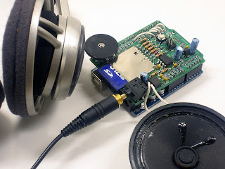
The mp3 shield is used to provide audio output which consists of the number of the bus which has just arrived at the bus stop. Even after the bus has passed by, it will continue to provide information about the bus which arrived the last. 

It can play up to 22KHz, 12bit uncompressed audio files of any length. It's low cost, available as an easy-to-make kit. It has an onboard DAC, filter and op-amp for high quality output. Audio files are read off of an SD/MMC card, which are available at nearly any store. Volume can be controlled with the onboard thumbwheel potentiometer.


Given below is a code which shows the mp3 shield initialization :

/*These header files are present in the WaveHC library which has to be imported to the libraries folder of the  Arduino IDE. This library can be obtained from https://code.google.com/p/wavehc/downloads/list */

#include <WaveHC.h>
#include <WaveUtil.h>

/* The WaveHC Library was developed for the Adafruit Arduino Wave Shield. It supports both standard SD and high capacity SDHC flash cards. The cards may be formatted with either FAT16 or FAT32 file systems.

The WaveHC Library is based on the four C++ classes, SdReader, FatVolume, FatReader and WaveHC.
SdReader is a standalone class that provides raw read access to standard SD cards and high capacity SDHC cards.

The FatVolume class provides access to data structures on FAT16 and FAT32 volumes.
File read access to FAT16 and FAT32 volumes is provided by the FatReader class.

The fourth class, WaveHC, is a modified version of Ladyada’s AF_Wave class that uses FatReader to read and play WAV files */


SdReader card;    // This object holds the information for the card
FatVolume vol;    // This holds the information for the partition on the card
FatReader root;   // This holds the information for the volumes root directory
FatReader file;   // This object represent the WAV file for a pi digit or period
WaveHC wave;      // This is the only wave (audio) object, since we will only play one at a time
/*
 * Define macro to put error messages in flash memory
 */
#define error(msg) error_P(PSTR(msg))

void setup()
{
      if (!card.init()) {
    error("Card init. failed!");
  }
  if (!vol.init(card)) {
    error("No partition!");
  }
  if (!root.openRoot(vol)) {
    error("Couldn't open dir");
  }

   PgmPrintln("Files found:");
   root.ls();
}

 The above piece of code will initialize the mp3 shield and check if the SD card is properly inserted, whether the .WAV files are present etc.  The files in the SD card are read using the Arduino SPI pins, which are :

Pin 10 - Slave Select
Pin 11-  MOSI
Pin 12 - MISO
Pin 13 - SCK

Pins 13, 12 and 11 are used to talk to the SD card and cant be changed. The rest of the pins, however, are more flexible. Connections of the other pins of the mp3 shield with the Arduino pins are given below:

Pin 2 - LCS
Pin 3 - CLK
Pin 4 - DI
Pin 5 - LAT
Pin 10 - CCS

In order to play a .WAV file, we use 4 functions - mp3play(), speaknum(), playcomplete() and playfile().
There are two files stored in the SD card namely, 1.WAV and 2.WAV. When bus 21 arrives at a bus stop the file 1.WAV will be played and if bus 22 arrives, 2.WAV will be played. 

Now we will describe each of these functions :

void mp3play(){
      speaknum(c);
        

This function will take a char input which will in turn call the speaknum function. 

void speaknum(char c) {
  uint8_t i=0;
  
  // copy flash string for 'period' to filename
  strcpy_P(filename, PSTR("P.WAV"));
  
  if ('0' <= c && c <= '9') {
    // digit - change 'P' to digit
    filename[0] = c;
    i = 1;
  } 
  else if (c != '.') {
    // error if not period
    return;
  }
  playcomplete(filename);
}

This function take the input char c and convert it to a string "c.WAV" and then call a function called playcomplete(filename). 

/*
 * Play a file and wait for it to complete
 */
void playcomplete(char *name) {
  playfile(name);
  while (wave.isplaying);
  
  // see if an error occurred while playing
  sdErrorCheck();
}

This function will call a function called playfile() and passes the filename that it receives as an argument to the function playfile() and it will wait until the file is played completely. It also calls a function sdErrorCheck() which checks if any errors occured while playing the file.

void playfile(char *name) {
  if (wave.isplaying) {// already playing something, so stop it!
    wave.stop(); // stop it
  }
  if (!file.open(root, name)) {
    PgmPrint("Couldn't open file ");
    Serial.print(name); 
    return;
  }
  if (!wave.create(file)) {
    PgmPrintln("Not a valid WAV");
    return;
  }
  // ok time to play!
  wave.play();
}


This function actually plays the file which it receives as the input. It checks to see if any other file is being played and stops it and then checks if the file can be successfully opened and and if the file is valid and then plays the file.

During the early stages in the embedded back end development, there were certain problems which we faced when we integrated the Adruino at the bus stop with an LED Matrix and the MP3 shield. So we made the the Slave select, MOSI, MISO, and SCK pins of the LED matrix different from what the SD card is using here and this problem was solved. 

Embedded Front End - Interfacing the LED Matrix

The LED matrix

The LED matrix is used to display information about the bus which last arrived on a bus stop. It is connected to the arduino board on each bus stop. It is used in this prototype for display purposes. It uses SPI communication to send the data from the arduino to the LED matrix. It is a 8X8 matrix and we can set all the 64 bits individually for displaying the bus number.
It can be directly connected to the hardware SPI pins of the arduino but since we were having problems due to the MP3 shield connected on the SPI as well, we had to use software SPI by bit banging the pins to emulate SPI communication. The MP3 shield was sending trash values to the LED matrix due to which it was not functioning properly. But for normal purposes, it might not be necessary unless there are problems like the ones we faced.


Connections with Arduino:


Code: This will explain how we can modify each bit in the LED matrix using software SPI. Alternatively hardware SPI is very much straightforward.

#define DATAOUT 11//MOSI - DI
#define SPICLOCK  13//sck - SCK
#define SLAVESELECT 10//ss - CS

char data [64] =
{
  1,1,1,1,1,1,1,1,
  1,1,1,1,1,1,1,1,
  1,1,1,1,1,1,1,1,
  1,1,1,1,1,1,1,1,
  1,1,1,1,1,1,1,1,
  1,1,1,1,1,1,1,1,
  1,1,1,1,1,1,1,1,
  1,1,1,1,1,1,1,1
};

void setup()
{
  SPCR = (1<<SPE)|(1<<MSTR)|(1<<SPR1);//Activate SPI HW, Master Mode, diviser Clock par 16

  pinMode(DATAOUT, OUTPUT);
  pinMode(SPICLOCK,OUTPUT);
  pinMode(SLAVESELECT,OUTPUT);

  digitalWrite(SLAVESELECT,HIGH);

  Serial.begin(9600);
}

void loop()
{
  transfer(data);
}

char spi_transfer(volatile char data)
{
  SPDR = data;
  while (!(SPSR & (1<<SPIF)))
  {
  };
  return SPDR;
}

void transfer(char myData[64]) {
  digitalWrite(SLAVESELECT, LOW);
  for(int i=0; i<64; i++){
    spi_transfer(myData[i]);
  }
  digitalWrite(SLAVESELECT, HIGH);
  delayMicroseconds(500);